Tuesday 31 August 2010

Jet Unit - Part 2

After the first test run of the boat, the jet unit was removed and inspected. The rear impeller boss had sheared off the shaft resulting in the rear impeller not turning which could explain the lack in performance towards the end of the day!!! The jet unit had a number of other issues as well such as excessive tip clearance, slightly bent shaft, worn thrust bearing, and bent impeller blades on the rear impeller. The decision to fully recondition the jet unit was therefore straightforward.

 Rear impeller boss sheared (broken piece visible in stator tunnel)
(click image to enlarge)

The image below shows the shaft assembly for the UA jet unit. The item below is actually my spare unit which I didn't want to use as the rear bearing arrangement is different (bronze bearing) and the impeller blades were in worse condition than the current unit.

 Complete shaft assembly (thrust bearing and UJ coupling at front)
(click image to enlarge)


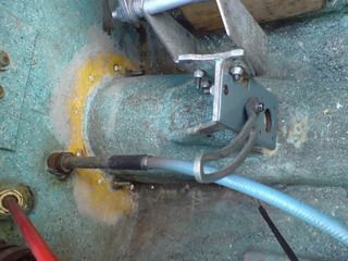
The thrust bearing is removed by removing the sleeve from the front of the shaft. This is located by a small grub screw. The allen key head was rusted out so this was drilled out. The sleeve then slides off. The thrust bearing can then be pulled off with a flywheel puller.

  Removal of thrust bearing and housing from shaft using flywheel puller
 (click image to enlarge)

The thrust bearing is a simple bronze casting with a sealed ball bearing retained by a large circlip. The bearing is sealed by 2 small oil seals at the rear of the bronze housing and one larger oil seal at the front of the housing. To remove the bearing the large oil seal is removed first. This was being replaced so it didn't matter if I damaged it whilst pulling it out. The circlip can then be removed using circlip pliers. The bearing must be pressed out, and cannot be pushed out by hand. I used the flywheel puller to do this.
Once the thrust bearing is out, the 2 smaller oil seals can be easily removed. All the seals were in bad condition and in need of replacement. I would suggest replacing the oil seals if in doubt as otherwise water and grit can destroy the thrust bearing.

Disassembled thrust bearing housing 
  (click image to enlarge) 

I ordered up new bearings and oil seals (water seals) from Nationwide Bearings http://www.nwideuk.com/.
The part numbers from Nationwide Bearings for the thrust bearing rebuild are:

  • Thrust bearing   63022RS
  • Small oil seal     OS125075025
  • Large oil seal     OS422507

New thrust bearings and oil seals

  (click image to enlarge) 

The rear bushing which supports the tail of the shaft is a marginally lubricated cylindrical bushing. The bushing is sealed by a further oil seal. This seal was also replaced. Again this part is available from Nationwide Bearings, Part Number OS352507.

Rear shaft bushing and oil seal (removed)

  (click image to enlarge) 

The jet pump housing was known to be in good condition as I had stripped it down before. Nevertheless, it had clearly seen some salt water use as there was some corrosion present. To prolong its life I decided to get the unit powdercoated. While doing this I also stripped down my spare unit and had this sandblasted to get an idea of its condition.

Jet unit (and spare unit) prior to blasting
  (click image to enlarge) 


 Jet unit (and spare unit to left) after blasting
  (click image to enlarge) 


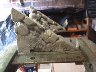
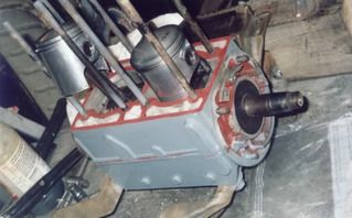
Before powdercoating I had the stator section machined to incorporate an alignment recess (see image below). This was a feature of my spare unit and allowed the partially protruding nozzle section wear ring to slot into the stator section of the jet unit, thus aligning the two sections of the jet unit along the centreline of the shaft. Aligning the two sections is otherwise a matter of trial and error and is the most frustrating part of fitting the jet unit to the boat.

The unit was powdercoated by RPA http://www.bristolmotorcyclepowdercoating.co.uk/index.html who did a great job of the old casting. It had to be heated (gassed) twice to get the trapped gas out of the porous casting before powdercoating. They then applied a primer coat followed by the gloss black final coat as recommended for marine applications. All the bearing surfaces and thread holes were masked off beforehand. The final coating is hard as rock, looks excellent, and should last a long time.

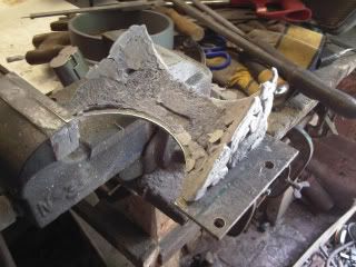
  Jet unit after powdercoating. Alignment recess on stator section visible (bare aluminium).
  (click image to enlarge) 


During the powdercoating process, the rear bushing for the shaft got damaged by the heating process. The bearing is of the marginally lubricated type (bronze outer with plastic inner). The plastic bearing surface was melted by the heat so I had to remove the damaged bearing and order a new one (these are available from Ondrives http://www.ondrives.com/index.php Length 25mm, Diameter 25mm, Part Number: PM-2525-DX). The new bearing is pressed into the rear housing (nozzle section).

Damaged rear bushing. Replacement bushing must be pressed in.
  (click image to enlarge)

To improve the performance of the boat, the main repair to the jet unit was to get the shaft straight. This had been straightened before but not enough, resulting in a small eccentricity which prevented the tip clearance between the impeller tips and the wear rings from being the correct dimension. The eccentricity also caused the impellers to contact the wear rings occasionally which could be felt through the boat at certain speeds. I took the dimensions of the original shaft and had a new one made up by Hamble Props http://www.hamblepropellers.com/. The new shaft is made from ultra strong Duplex Stainless Steel and has a slightly increased diameter to further improve strength. The impeller blades were bent in several places and Hamble Props were able to straighten these out to the original shape.

New wear rings were made up from ABS plastic to match the impeller diameter by Plastic Machining Services, Telford http://www.plasticmachiningservices.co.uk/. A tip clearance of 0.2mm was specified. Any further tip clearance reduction was considered to provide insufficient clearance for the natural vibration and flexing of the shaft. The wear rings were pressed into the housings and are held in place through an interference fit.


Wednesday 24 February 2010

Launch Day 2

More photos from first run. I didn't fiddle with the engine settings so can go quite a bit leaner on the fuel mix and also dial in some more advance timing on the MSD ignition. I ran a conservative map at 20degrees advance ignition timing out of an estimated maximum 25 degrees. Standard igntion timing is fixed at 18degrees +/- 2 degrees.


Aim for the middle of the lake!
(click photo to enlarge)
 
 
Britannia rules the waves!!  Red ensign from my Dads old Fletcher speedboat.
(click photo to enlarge)

 (click photo to enlarge)

 (click photo to enlarge)

 (click photo to enlarge)

Boating heaven!
 (click photo to enlarge)

 (click photo to enlarge)

 (click photo to enlarge)

 (click photo to enlarge)

(click photo to enlarge)

Saturday 13 February 2010

Launch Day

The boat finally got wet at the end of October 2009. I was very lucky to be able to use a local lake to test the boat. The lauch went well and no leaks were found. After the naming ceremony (where she was named "Soap Dish") it was time to start the engine a go for a spin. The engine started on the button and everything seemed in order. Once she was warmed up, i took her out and tested the steering and then after tootling around for a bit, tried to get her up on the plane. It quickly became appartent that the jet unit had some major problems as the jet would slip as more throttle was applied. A quick burst of throttle only produced a load of bubbles, but did not result in any decent acceleration. To get the thing on the plane, i had to feed the throttle in gently, but there remained the sensantion that the jet unit was not running well and could be likened to the feeling of the clutch slipping in a car. The problem was put down to the tip clearance around the impellers (the distance between the impeller tips and the wear rings). After the run the jet unit was disassembled and the tip clearance was found to be way too big (about 2mm). The recommended tip clearance for jet units is about 0.2mm. I was aware the tip clearance was big but had not expected such a drop in performance and had deliberately left the tip clearance as it was to account for the small eccentricity in the shaft. The jet unit has now been removed and is undergoing a full rebuild with a new Duplex Stainless Steel shaft and new wear rings sized to give the correct tip clearance.

At the top of the slipway ready for launch!


In the water again, after years in the shed

New Trailer

The boat had spent many months on some old tires as the old trailer was about to fall apart. The trailer would have needed a complete rebuild and as I didn't have that much time to work on it, so I decided to fork out for a new one. I found a suitable trailer from Indespension, which is actually a Jet Ski trailer, which fits the boat well. It sits a bit higher than the old trailer which makes it easier to work on.

The boat sat on old tires awaiting new trailer


Up on new trailer an ready for the water


Engine Test Run

Having wired up the electrics and made all the necessary connections for the rebuilt engine, it was time for a test run. Up until this point the engine had been very unreliable when it came to starting so it was very satisfying when it started first time on the new ignition system and rebuilt carb. I connected the garden hose to the engine to keep the engine temps in check, which is fine if you remember to turn it off before stopping the engine, otherwise water flows into the cylinders from the exhaust.

Sunday 7 February 2010

Making a new intake scoop

The original intake scoop which form part of the jet unit intake was missing so a new one had to be built from scratch. This was done by cutting a suitably sized steel base plate, and then building up the shape of the scoop with expanding foam filler. The foam was then cut to the required shape and glassed over with several layers of glass fibre.


Expanding foam used to form rough shape of scoop


Mold removed


Cutting leading edges to shape


Shaping the foam


Adding fibrefiller to smooth out the foam


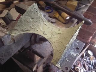
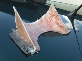
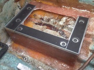
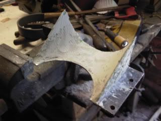
Smoothing out the filler. Starting to take shape


Final stages of fairing


First layer of glass


Wednesday 3 February 2010

Making a Battery Tray

All there was to hold the battery in place was an old bit on 2 x 4 and some metal bar which weren't even properly attached to the hull so I set about making a new battery tray, properly glassed in.


Before - Obvius place for battery but no tray

Making the mold - I used Beeswax as a release agent - different, but it worked!


Laying up the glass


Plug removed from mold


Tidied up and ready to be glassed into hull


Glassed into hull and rubber matting added

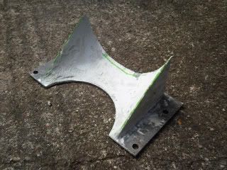
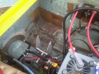
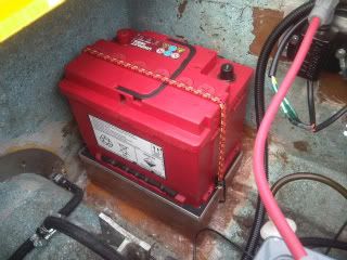
Battery in position - just needs proper clamp to hold it in place now

Monday 25 January 2010

Dashboard - Fitting an extra Volts gauge

The standard boat only had a water temp gauge to keep an eye on the engine temps. Because I had fitted a total loss ignition system (i.e. a system that pulls power directly from the battery, rather than the ignition systems own charging system, as was the case for the original engine) I wanted to fit an extra gauge to measure the voltage of the battery.

The new gauges are manufactured by STACK. The temp gauge came with all the fittings for the sensor to mount to the engine. The quality of the gauges and senders etc was very impressive.

I had originally fitted a SPA digital water/volts dual gauge (both read outs in one gauge) but the EM pulses given off by the ignition system interfered with the digital gauge wiring and stopped it from working. The new mechanical temp gauge has the benefit of not needing a power supply and having a very fast response time. I haven't wired the backlighting into the gauges yet, a job for another day (fiddling around behind the dash is tricky).


Drilling a new hole for the water temp gauge

STACK Battery Volts and Water Temp Gauges in place

Friday 22 January 2010

Jet Unit - Part 1

I didn't know much about jet units before embarking on this project but i knew enough to realise that it had at some point in its life sucked up a decent size stone which had removed much of the trailing edge of the stator blades between the two impellers. Not an easy fix, especially with no welding gear so i gave the middle section of the pump to a friend, who gave it to an ex Rolls Royce mechanic who was a bit of a dab hand at Ali welding. He did a top job at repairing the missing areas of the blades by welding layer over layer. I then set to with the Dremel drill to profile the blades back to their original shape. This took ages and a lot of patience but got a good result in the end.


Stator section of jet pump after having missing chunks welded up

The rest of the jet pump seemed OK, but the wear rings were quite worn so I had some more made up by Plastic Machining Services of Telford. I later discovered that I had specified WAY too big a tip clearance (approx 2mm total) resulting in poor performance from the jet pump. The wear rings were pressed into the pump housings and the unit was treated to a coat of matt black enamel paint.


UA Jet unit following initial refurb

Upon assembly of the unit and fitment to the boat I discovered that the shaft was slightly bent, so I had this straightened but unfortunately it was not straight enough and I encountered some bad vibration when the impellers hit the wear rings at certain speeds. This, combined with the big tip clearance on the impellers resulted in poor performance from the jet on its first test run.

The intake to the jet unit is fibreglass and is part of the hull moulding (see pic below). My boat didn't come with an intake grate to prevent stones being taken up into the jet but the hull moulding has the slots for an intake grate. I managed to buy another UA jet unit on ebay which came with an intake grate so I will eventually fit that to the boat.


Inlet into jet unit

Wednesday 20 January 2010

Engine

First things first.... Try to start the engine.

This quickly established problem number one, the starter motor slipping out because of worn teeth on the flywheel as well as poor engagement from the starter motor.

So the first few jobs were to fix the starter motor clutch and refurb the starter motor. The flywheel was also set back by adding a shim to get better contact with the starter motor drive. Having sorted the starter motor, and temporarily fixed the flywheel, the next problem was the ignition system.

The engine originally had a CDI magnet ring type ignition. These produce a huge spark and don't require an alternator as they produce their own power. This had obviously broken and was replaced by the previous owner who made up a distributorless points ignition system working on the wasted spark principle (2 sparks per cylinder for every rotation). The home made ignition system produced a weak spark and made starting the engine very difficult. The previous owner had obviously had some major issues getting the engine/boat to work as when I looked at the cam/points cover (see pic) he had stamped the words "ABANDON ALL HOPE ALL YE WHO ENTER HERE" onto the inside of the cover. Amusing at the time but if i'd found it earlier, i'd probably have taken this excellent advice!


Hidden advice from the previous owner! Look closely...


Anyway, the chap who sold it to me suggested I strap a magneto ignition system to it, such as the types seen on old Mercury outboards. Not knowing any better, I took his advice. It involved tracking down the magneto off someone in Wales, making a bracket and toothed pulley belt system, and the necessay adjustment holes etc. IT WORKED. It fired up nicely and was running much better however the system was eventually ditched because the bracket holding the magneto to the engine vibrated to the point that you could barely see the magneto as it attempted to destroy itself. So I removed the magneto and the bracket and started again. This time it was back to points, except I used the points as a trigger for a home made electronic ignition system which I soldered up from a Maplin kit. I hoped this would help give a better spark in combination with a new coil. The points system failed to generate a good spark however despite using new plugs (the correct ones this time), new leads, and the electronic box coupled to the new coil. I got the thing to start a couple of times but it really was hard work to start. I then made the mistake of coaxing the thing into life using "Easy Start" which led to one of the piston rings going on holiday via the exhaust pipe. This meant an engine rebuild, so i sourced new pistons and rings, gaskets etc from Andover Norton (Rotax Suppliers) and set to. I also stripped the carb and found that some parts were missing altogether and the main needle very badly worn.


The Rotax engine in its early days with Mk1 ignition system - later ditched due to bad vibration

Engine rebuild in progress - NEVER USE EASY START ON OLD ENGINES!!!


So with the engine rebuilt, it was time to fit an ignition system that actually worked, and sort the carb. I ordered an MSD ignition system designed specifically for small watercraft. The MSD system has modern trigger pickups to trigger the sparks via 2 coils, as well as digital timing control allowing the ignition to be retarded at start up for easy starts, and advanced at higher revs to give more power. It also has a rev limiter to prevent engine damage at high revs. The ignition computer also sends multiple sparks (MSD = Multiple Spark Discharge) to each spark plug below 3000rpm, improving the idle and start. To fit the MSD igntion to this custom application I had to have a mounting plate fabricated to seat the trigger pickups. I also at this point decided to have a new flywheel made up as the old flywheel had worn teeth and was way out of balance, causing the engine to vibrate. I designed a heavier flywheel to aid starting and to give a nice smooth performing engine. The trigger plate and flywheel were fabricated by TTV Racing who did a great job and were very helpful.

New MSD digital programmable ignition system


Old mangled and off balance flywheel


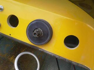
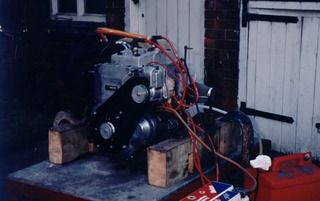
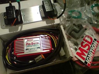
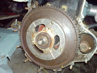
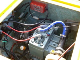
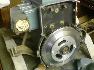
Rebuilt engine with custom made flywheel following "Easy Start" disaster. A magnetic trigger is installed on the rear face of the flywheel to trigger the ignition sparks

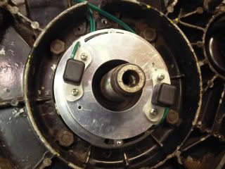
Custom made trigger pickup mounting plate and twin trigger pickups. These control the twin coil packs

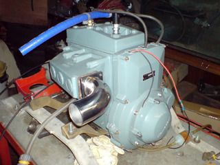
With new exhaust header and ignition cover (from a Kawasaki)

With the ignition system sorted, it was time to sort the carb. I ordered a full set of replacement parts from a very helpful and top bloke called Ralph Engelbrecht, a specialist from Germany with a good supply of BING carb parts. I also discovered the fuel pump wasn't working properly, and ordered a replacement.


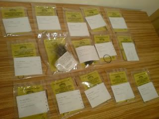
New parts from BING carburettors - They have lots of old spares in stock!


Old carb float being removed

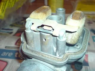
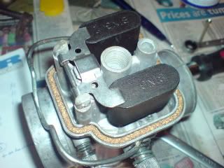
New float being fitted to carb - also fitted new jets, needles, and missing parts!


The engine then went into the boat and all the wiring for the new ignition system was connected up using waterproof Perma Seal connectors and Deutsch connectors. I replaced the fuel lines and fitted new in-line fuel filters. The engine fired up first time and now provides reliable first time starts every time and runs beautifully. Well worth the money and time for the ignition and carb parts.

Everything in place and wiring done